contents
1.Overview
2.Introduction to transmission lines
3.Component of Transmission Line
3.1
conductor
3.2 Earth
wire
3.3
Insulator
3.4
Transmission Tower
3.5 Wave
trap and other hard war
4. Skin effect
5.Corona effect
6.Ferranti effect
7..Design specifications
8.Types of Transmission Lines
8.1 Two wire transmission line
8.2 Co-axial transmission line
8.3 Wave
Guide
8.4 Micro
Strip
9. Factors determining transmission line
10.Economic
voltages of transmission of power
11. Types of
conductors
11.1
AAC : All Aluminium Conductor
11.2
AAAC : All Aluminium Alloy Conductor
11.3
ACSR : Aluminium Conductor, Steel
Reinforced
11.4
ACAR : Aluminium Conductor, Alloy Reinforced
12. Factors determining conductor sizes
13. Performance
of Transmission Lines
14. Poles and
types of poles
15.Towers and
Tower accessories
16.
Protection of tower footing
17. Earthing
18.Types of
insulator
18.1 Pin
Insulator
18.2
Suspension Insulator
18.3
Strain Insulator
19. Clearances
20. BOQ of 33 kv transmission line
21.Types of fault in electrical power system
22.Testing and Commissioning
19. Clearances
20. BOQ of 33 kv transmission line
21.Types of fault in electrical power system
22.Testing and Commissioning
23.General
application
24..General
considerations
1.
OVERVIEW
Ordinary electrical cables suffice to carry
low frequency alternating current (AC), such as mains power, which reverses
direction 100 to 120 times per second, and audio signals. However, they cannot
be used to carry currents in the radio frequency range or higher, which reverse
direction millions to billions of times per second, because the energy tends to
radiate off the cable as radio waves, causing power losses. Radio frequency
currents also tend to reflect from discontinuities in the cable such as
connectors and joints, and travel back down the cable toward the source. These
reflections act as bottlenecks, preventing the signal power from reaching the
destination. Transmission lines use specialized construction, and impedance
matching, to carry electromagnetic signals with minimal reflections and power
losses. The distinguishing feature of most transmission lines is that they have
uniform cross sectional dimensions along their length, giving them a uniform
impedance, called the characteristic impedance, to prevent reflections. Types
of transmission line include parallel line (ladder line, twisted pair), coaxial
cable, stripline, and microstrip. The higher the frequency of electromagnetic waves
moving through a given cable or medium, the shorter the wavelength of the
waves. Transmission lines become necessary when the length of the cable is
longer than a significant fraction of the transmitted frequency's wavelength.
At microwave frequencies and above, power losses in transmission lines become excessive, and wave guides are used instead, which function as "pipes" to confine and guide the electromagnetic waves.Some sources define wave guides as a type of transmission line; however, this article will not include them. At even higher frequencies, in the terahertz, infrared and light range, wave guides in turn become loss, and optical methods, (such as lenses and mirrors), are used to guide electromagnetic waves.
The theory of sound wave propagation is very similar mathematically to that of electromagnetic waves, so techniques from transmission line theory are also used to build structures to conduct acoustic waves; and these are called acoustic transmission lines.
2. INTRODUCTION TO TRANSMISSION LINES
A transmission line is a pair of electrical
conductors carrying an electrical signal from one place to another. Coaxial
cable and twisted pair cable are examples. The two conductors have inductance
per unit length, which we can calculate from their size and shape. They have
capacitance per unit length, which we can calculate from the dielectric
constant of the insulation. In the early days of cable-making, there would be current
leaking through the insulation, but in modern cables, such leakage is negligible.
The electrical resistance of the conductors, however, is significant because it
increases with frequency. The magnetic fields generated by high-frequency
currents drive those currents to the outer edge of the conductor that carries
them, so higher the frequency, the thinner the layer of metal available to
carry the current, and the higher the effective resistance of the cable. In
this discussion, we derive and demonstrate the equations that govern the
propagation of waves down a transmission line, and show how the
frequency-dependent resistance of these cables gives rise to attenuation and
distortion of high-frequency signals.
3. Component of Transmission line
3.1 CONDUCTOR:
In physics and electrical engineering, a
conductor is an object or type of material that allows the flow of an electrical
current in one or more directions. A metal wire is common electrical
conductor.
In
metals such as copper or aluminum, the mobile charged particles are electron Positive
charges may also be mobile, such as the cationic electrolyte(s) of a battery or the mobile protons of the proton
conductor of a fuel cell. Insulators are non-conducting materials with few
mobile charges that support only insignificant electric currents.
Overhead
conductors carry electric power from generating stations to customers:
Properties:
1.High electrical conductivity(low resistivity).
2.High tensile strength(with stand mech stress).
3.Low specific gravity(weight/volume low).
4.Low cost (use for long distances).
5.The electric field inside the coonductor is zero.
6.The charge density inside the conductor is zero.
3.2 Earth wire :
Ground wires are bare
conductors supported at the top of transmission towers. They serve to shield
the line and intercept lighting stroke before it hits the current carry in conductors
below. Ground wires normally do not carry current. Therefore, they are often
made of steel. The ground wires are solidly connected to ground at each tower in
transmission and distribution system.

3.3 Insulator:
An electrical
insulator is a material whose internal electric charges do not flow freely, and
therefore make it nearly impossible to conduct an electric current under the influence
of an electric field. This contrasts with other materials, semiconductors and conductors,
which conduct electric current more easily. The property that distinguishes an
insulator is its resistivity; insulators have higher resistivity than semi conductor
A perfect insulator does not exist, because even insulators contain small
numbers of mobile charges (charge carriers) which can carry current. In
addition, all insulators become electrically conductive when a sufficiently
large voltage is applied that the electric field tears electrons away from the
atoms. This is known as the breakdown voltage of an insulator. Some materials
such as glass, paper and Teflon, which have high resistivity, are very good
electrical insulators. A much larger class of materials, even though they may
have lower bulk resistivity, are still good enough to prevent significant
current from flowing at normally used voltages, and thus are employed as insulation
for electrical wiring and cables. Examples include rubber-like polymers and most plastics.

3.4 Transmission Tower:
A
transmission tower or power tower (electricity pylon in the United Kingdom and
parts of Europe) is a tall structure, usually a steel lattice tower, used to
support and overhead power line. They
are used in high-voltage AC and DC systems, and come in a wide variety of shapes
and sizes. Typical height ranges from 15 to 55 m (49 to 180 f t), though the tallest
are the 370 m (1,214 f t) towers of a 2,700 m (8,858 f t) span of Zhoushan
Island Overhead Power line Tie. In addition to steel, other materials may be
used, including concrete and wood.
There
are four major categories of transmission towers suspension, terminal tension,
and transposition. Some transmission towers combine these basic functions. Transmission
towers and their overhead power lines are often considered to be a form of
visual pollution. Methods to reduce the visual effect include under grounding.

.
3.5 Wave trap and
other hard wav:
Wave trap
is a parallel tuned inductor - capacitor 'tank' circuit made to be resonant at
the desired communication frequency. It is the effort to utilize the same
transmission line between two substation for the purpose of communications. At
this communication frequencies the tank ckt provides high impedance and does
not allow to pass through them & on to the substation bus &
into transformers.

4. Skin Effect
The
alternating current flowing through the conductor is non-uniformly distributed
throughout its length. This is because the outer strands of the conductor
(i.e., the strands which form the surface of the conductor) carry more current
than the inner strands (i.e., the strands which are closer to the center of the
conductor). This non-uniform distribution of current causes an increase in the
resistance of the conductor to the flow of alternating current. This effect is
known as skin effect and it shown in figure.
This effect is termed because skin effect as
the charges flow through the surface
(skin) and not through the center of the conductor. The
skin effect is absent when the current is DC this is because the direct current
flowing through a conductor spreads uniformly throughout the cross—sectional area of conductor.
.

Why Skin Effect Occurs in Transmission Lines?
The main
cause of skin effect is the non-uniformity of flux linkage. The phenomenon of
skin effect can be explained as follows:
Consider a
multi—stranded conductor composed of ‘n’ number of strand (filaments). The AC
current flowing through the inner strands produce flux which links (enclose)
the inner strands only. But, the flux produced by the flow of AC current
through the outer strands, links (enclose) not only the outer strands but also
the inner strands. Thus,, the flux linkage per ampere to the inner strands is
higher than the flux linkage per ampere to the outer strands. This causes the inductance
(and hence inductive reactances ) of
inner strands to be much higher than for the outer strands. Thus, higher the
impedance lower » is the flow of current. As a result, the outer strands carry
more current than the inner strands.
Factors Affecting Skin Effect in Transmission
Lines
Skin effect primarily depends on the three important
factors,
1. Operating frequencies
2. Size of conductor
3. Type of conductor.
Higher the
operating frequency, the greater is the skin effect. The diameter of conductor
has a direct relation with skin effect. Bigger the diameter of conductor,
higher is the skin effect. The type of conductor also decides the level of skin
effect. The skin effect is less in case of a stranded conductor than a solid
conductor.
5. Corona Effect
For
overhead transmission system the atmospheric air, which is the dielectric
medium, behaves practically like a perfect insulator when the potential
difference between the conductor is small. If the voltage impressed between the
conductor is of alternating nature, the charging current will flow due to the
capacitance of the lines. This charging current increases the voltages of the
lines and corresponding increase the electric field intensity of the lines.
When the
value of electric field intensity is less than 30kV (disruptive voltage), the
flow of current between two conductors of the lines is negligibly small. But
when the electric field intensity reaches this critical value or disruptive
voltage the airs between the conductors get ionizes and becomes conducting. If
the voltage goes on increasing spark is established between the conductors
until the complete breakdown of the insulating properties of the material.
This
phenomenon of ionization of surrounding air around the conductor due to which
luminous glow with hissing noise is rise is called corona effect.
Corona Formation:
Air is not perfect insulator and even under
normal condition, the air contains many free electrons and ions. When an
electric field intensity is established between the conductors, these ions and
free electrons experience force upon them. Due to this force, the ions and free
electrons get accelerated and moved in the opposite direction.
The
charged particles during their motion collide with one another and also with
the very slow moving uncharged molecules. Thus, the number of charge particles
goes on increasing rapidly. This increase the conduction of air between the
conductors and a breakdown occurs. Which established the arc or discharge between the conductors.
.
Factors
affecting corona:
Corona loss depends on a large number of
factors, the most important being broadly classified in the following way:
Effect of
supply voltage – If the supply voltage
is high corona loss is higher in the lines. In low voltage transmission lines
the corona is negligible, due to the insufficient electric field to maintain
ionization.
The
condition of conductor surface – If the conductor is smooth, the electric field
will be more uniform as compared to the rough surface. The roughness of
conductor is caused by the deposition of dirt, dust and by scratching, etc.
Thus, rough line decreases the corona loss in the transmission lines.
Air
Density Factor – The corona loss in inversely proportional to air density
factor, i.e., corona loss, increase with the decrease in density of air.
Transmission lines passing through a hilly area may have higher corona loss
than that of similar transmission lines in the plains because in a hilly area
the density of air is low.
Effect of system voltage – Electric field
intensity in the space around the conductors depends on the potential
difference between the conductors. If the potential difference is high,
electric field intensity is also very high and hence corona is also high.
Corona loss, increase with the increase in the voltage.
A spacing
between conductors – If the distance between two conductors is much more as
compared to the diameter of the conductor than the corona loss occurs in the
conductor. If the distance between them is extended beyond certain limits then
the dielectric medium between them get decreases and hence the corona loss also
reduces
.
6. Ferranti Effect
Definition:
A long transmission line has a large
capacitance. If such a line is open-circuited or connected to the very light
load at the receiving end, the magnitude
of the voltage at the receiving end becomes higher than the voltage at the
sending end. This phenomenon is called Ferranti effect.
Ferranti
effect is due to the charging current of the line. When an alternating voltage
is applied, the current that flows into the capacitor is called charging
current. A Charging current is also known as capacitive current.
.
Why Ferranti effect occurs?
Capacitance and inductance are the main parameters of the lines having a
length 240km or above. On such transmission lines, the capacitance is not
concentrated at some definite points. Itis distributed uniformly along the
whole length of the line.
When
the voltage is applied at the sending end, the current drawn by the capacitance
of the line is more than current associated with the load. Thus, at no load or
light load, the voltage at the receiving end is quite large as compared to the
constant voltage at the sending end.
How to reduce Ferranti effect:
Electrical devices are designed to work at some particular voltage. If
the voltages are high at the user ends their equipment get damaged, and their
windings burn because of high voltage. Ferranti effect on long transmission
lines at low load or no load increases the receiving end voltage. This voltage
can be controlled by placing the shunt reactors at the receiving end of the
lines.
Shunt
reactor is an inductive current element connected between line and neutral to
compensate the capacitive current from transmission lines. When this effect
occurs in long transmission lines, shunt reactors compensate the capacitive of the lines and therefore the voltage is
regulated within the prescribed limits.
7. DESIGN SPECIFICATIONS
The towers and conductors of a transmission
line are familiar elements in our landscape.However, on closer inspection, each
transmission line has unique characteristics that have correspondingly unique
implications for the environment. In this section, we list design
specifications (line characteristics) that are commonly required to define a
transmission line. Many of these specifications have implications for the net
environmental effects. For the purpose of this report, a range of values is
considered for these specifications, with the exception that a fixed nominal
voltage of 500 kV is assumed.
Overall Descriptive Specification:
The most basic descriptive specifications
include a line name or other identifier, nominal voltage, length of line, altitude
range, and the design load district. The line identifier is commonly taken from
endpoint names, e.g., Inland−Macedonia on the Cleveland Electric Illuminating
Co. system. The endpoint names are generally geographic points, but may be
substation names or major industrial facilities. The nominal voltage is an
approximation to actual line voltage that is convenient for discussion. Actual
voltage will vary according to line resistance, distance, interaction with
connected equipment, and electrical performance of the line. For AC lines, the
nominal voltage is close to the RMS (root mean square) voltage.The altitude
range is a rough surrogate for weather and terrain. This is important, since
nearly all aspects of line design, construction, and environmental impacts are
linked to weather. The design load district is another surrogate for weather.
These districts are defined by the National Electrical Safety Code (NESC) and
by some local jurisdictions. These districts include NESC Heavy Loading, NESC
Medium Loading, NESC Light Loading, California Heavy Loading, and California
Light Loading. The design wind and ice loading on lines and towers is based on
the design load district. This affects insulator specifications as well as
tower dimensions, span lengths, tower design, and conductor mechanical strength
and wind dampening.
Tower Specifications:
The towers support the conductors and
provide physical and electrical isolation for energized lines. The minimum set
of specifications for towers are the material of construction, type or
geometry, span between towers, weight, number of circuits, and circuit
configuration. At 500 kV, the material of construction is generally steel,
though aluminum and hybrid construction, which uses both steel and aluminum,
have also been used. The type of tower refers to basic tower geometry. The
options are lattice, pole (or monopole), H-frame, guyed-V, or guyed-Y. The span
is commonly expressed in the average number of towers per mile. This value
ranges from four to six towers per mile. The weight of the tower varies
substantially with height, duty (straight run or corner, river crossing, etc.),
material, number of circuits, and geometry. The average weight of 670 towers
for 500-kV lines included in the EPRI survey (EPRI 1982) is 28,000 lb. The
range of reported tower weights is 8,500 to 235,000 lb. The type of tower(specific
tower geometry) is very site-dependent, and, for any given conditions, multiple
options are likely to exist. The next section provides some illustrations of
specific tower types and describes their relative impacts. The number of
circuits is generally either one or two. The circuit configuration refers to
the relative positioning of conductors for each of the phases. Generally the
options are horizontal, vertical, or triangular. The vertical orientation
allows for a more compact ROW, but it requires a taller tower.
Minimum Clearances:
The basic function of the tower is to
isolate conductors from their surroundings, including other conductors and the
tower structure. Clearances are specified for phase-to-tower, phase to ground,
and phase-to-phase. Phase-to-tower clearance for 500 kV ranges from about 10 to
17 feet, with 13 feet being the most common specification. These distances are
maintained by insulator strings and must take into account possible swaying of
the conductors. The typical phase-to-ground clearance is 30 to 40 feet. This
clearance is maintained by setting the tower height, controlling the line
temperature to limit sag, and controlling vegetation and structures in the ROW.
Typical phase-to-phase separation is also 30 to 40 feet and is controlled by
tower geometry and line motion suppression.
Insulators:
Insulator
design varies according to tower function. For suspension towers (line of
conductors is straight), the insulator assembly is called a suspension string.
For deviation towers (the conductors change direction), the insulator assembly
is called a strain string. For 500-kV lines, the insulator strings are built up
from individual porcelain disks typically 5.75 inches thick and 10 inches in
diameter. The full string is composed of 18 to 28 disks, providing a long path
for stray currents to negotiate to reach ground. At this voltage, two to four
insulator strings are commonly used at each conductor connection point, often
in a V pattern to limit lateral sway.
Lightning Protection:
Since the towers are tall, well-grounded
metallic structures, they are an easy target for lightning. This puts the
conductors, other energized equipment, and even customer equipment at high
risk. To control the effects of lightning, an extra set of wires is generally
strung along the extreme top points of the towers. These wires are attached
directly to the towers (no insulation), providing a path for the lightning
directly to and through the towers to the ground straps at the base of the
towers. The extra wires are called shield wires and are either steel or
aluminum-clad steel with a diameter of approximately ½ inch.
Conductor Motion Suppression:
Wind-induced conductor motion, aeolian
vibration, can damage the conductors. A variety of devices have been employed
to dampen these oscillatory motions. By far, the most common damper style on
500 kV lines is called the Stock bridge damper. These devices look like
elongated dumbbells hung close to and below the conductors, a few feet away
from the point of attachment of the conductors to the tower. The weighted ends
are connected by a short section of stiff cable, which is supported by a clamp
to the conductor immediately above. Dampers can prevent the formation of
standing waves by absorbing vibrational energy. Typically, a single damper is
located in each span for each conductor.
8. Types of Transmission Lines
8.1 Two wire transmission line:
This
transmission line consists of a pair of parallel conducting wires separated by
a uniform distance .These are used in power systems or telephones lines.

8.2 Coaxial transmission line:
This consists of an inner and a coaxial outer conducting sheath
separated by a dielectric medium . They are used as TV cables, telephones
cables and power cables.

8.3 Parallel plate transmission line or
planar line:
It
has two parallel conducting plates separated by a dielectric slab of uniform
thickness  \\
\\

\\
8.4 Micro strip transmission line:
It
consists of core and cladding . Information passes through the core in the form
of totally internal reflected TEM waves.

9.FACTORS DETERMINING TRANSMISSION LINES
some factors to be
considered when selecting the transmission line conductors include:
1.Required sag and span
between conductors.
2.Tension on the
conductors.
3.whether or not the
temperature is corrosive.
4.whether or not the
line is prone to vibration.
5.power loss allowed on
the line.
6.voltage loss allowed
on the line.
7.climate at the line
location.
10.
Economic Choice Of Transmission Voltage
While
designing any transmission line, economy is one of the most important factors
the engineer must consider. An electrical power transmission line must be
designed in such a way that the maximum economy is achieved. Economics of
electric power transmission is influenced by various factors such as the right
of way, supporting structures, conductor size, transmission voltage etc.
Transmission voltage closely influences the economics of power transmission.
Generally, electric power is transmitted using 3-phase AC system at high
voltages. Before studying how to choose economic transmission voltages, one
should know the advantages and limitations of high voltage transmission.
Advantages Of High Voltage
Transmission:
Efficient transmission of larger amounts of
power:
In a 3 phase AC system, power is calculated as
P=√3*VIcosɸ. It is clear that, for a large amount of power to be transmitted at
a lower voltage, the amount of current will be very large. Let's take an
example, 200 MW of power is to be transmitted at 11kV and consider cosɸ = 0.8
lagging. In this case, the amount of current that will flow through the line
would be 200,000,000 / (√3 * 11,000 * 0.8) ≈ 13,122 A. For safely carrying this
much large current, a conductor with very large diameter or much more number of
conductors in bundled form may be required. And if the same power is
transmitted at 220kV, the current would be 200,000,000 / (√3 * 220,000 * 0.8 )
≈ 656 A. As the power lost in a conductor is given as I2R, you can see large
saving in losses can be achieved by transmitting electricity at higher
voltages. From this example, it is clearly not feasible and practical to
transmit larger power at lower voltages. Also, transmission of electricity at
higher voltages is more efficient.
Saving
in conductor material: As shown above, for the same amount of power transmitted
at a higher voltage the current will be relatively lower. Current carrying
capacity of a conductor depends on the diameter of the conductor (conductor
size) along with few other factors. That means, for larger currents to be
transmitted, the conductor size must be larger. Hence, transmitting power at
higher voltages will reduce the amount of current to be carried and
consequently the required conductor size would also be lesser.
Improved voltage regulation:
Decreased current will also result in
decreased voltage drop across the line. Voltage regulation is defined as
(VS - VR)/VS. As voltage drop is
decreased, the difference between sending end voltage and receiving end voltage
is also decreased. Thus, voltage regulation is improved
.
.
Limitations Of High Transmission
Voltage
With increase
in the transmission voltage
· . 1. cost of insulators increases
·
2.cost of transformers increases
·
3.cost of switch gear increases
·
4.cost of lightning arrestor increases
·
cost of support towers increases (as
taller towers with longer cross arms are required)
Economic Choice Of Transmission Voltage
From the above advantages and limitations
of high voltage transmission, we can say that with increase in transmission
voltage the cost of conductor material can be reduced and the efficiency can be
increased. But the cost of transformers, insulators, switchgear etc. is
increased at the same time. Thus, for overall economy, there is an optimum
transmission voltage. The limit to use of higher transmission voltage is
reached when the saving in cost of conductor material is offset by the
increased cost of transformers, switchgear, insulators etc. The economical
transmission voltage is one for which the sum of cost of conductor material,
transformers, switchgear, insulators and other equipment is minimum.
If the power to be transmitted and the
length of transmission are known, calculations are made for various
transmission voltages. Initially, some standard transmission voltage is
selected and the relative total cost of equipment is determined. A graph is
drawn for the total cost of transmission with respect to various transmission
voltages as shown in the figure at right. The lowest point on the curve gives
the optimum transmission voltage. As here in the graph, point P is the lowest
and the corresponding voltage OA is the optimum transmission voltage.
The above method of finding economical
transmission voltage very rarely used as it is hard to pre-determine the costs
of various equipment. Instead, an empirical formula, according to the American
practice, is used. According to this formula, an economical transmission voltage
for a 3 phase AC system is given as,
formula for economic
choice of transmission voltage
Where, V = line voltage
in kV
P = maximum power per phase (in kW) to
be delivered over single circuit
L = distance of transmission in km
Economical transmission voltage depends on
the power to be transmitted and the length of transmission. If the power to be
transmitted is large, cost per kW of terminal equipment reduces. This results
in increased economic transmission voltage. If the distance of transmission is
increased, saving in the cost of conductor material can be significantly
increased by increasing the transmission
voltage.
 .
.
voltage.
.
11.TYPES OF CONDUCTORS
A conductor is one of the most important
components of overhead lines. Selecting a proper type of conductor for overhead
lines is as important as selecting economic conductor size and economic
transmission voltage. A good conductor should have the following properties:
· 1.
high electrical conductivity
· 2.. high tensile strength in order to
withstand mechanical stresses
· 3.
relatively lower cost without
compromising much of other properties
·
lower weight per unit volume
1 11.1 ASC : Aluminium Standard Conductor
This type is sometimes also referred as
ASC (Aluminium Stranded Conductor). It is made up of strands of EC grade or
Electrical Conductor grade aluminium. AAC conductor has conductivity about 61%
IACS(International Annealed Copper Standard). Despite having a good
conductivity, because of its relatively poor strength, AAC has limited use in
transmission and rural distribution lines. However, AAC can be seen in urban
areas for distribution where spans are usually short but higher conductivity is
required.

11.2 AAAC : All Aluminium Alloy Conductor
These conductors are made from aluminium
alloy 6201 which is a high strength Aluminium-Magnesium-Silicon alloy.This
alloy conductor offers good electrical conductivity (about 52.5% IACS) with
better mechanical strength. Because of AAAC's lighter weight as compared to
ACSR of equal strength and current capacity, AAAC may be used for distribution
purposes. However, it is not usually preferred for transmission.
Also,AAACconductors can be employed in coastal areas because of their excellent
corrosion resistance.

11.3 ACSR : Aluminium Conductor, Steel Reinforced
ACSR consists of a solid or stranded steel
core with one or more layers of high purity aluminium (aluminium 1350) wires
wrapped in spiral. The core wires may be zinc coated (galvanized) steel or
aluminium coated (aluminized) steel. Galvanization or aluminization coatings
are thin and are applied to protect the steel from corrosion. The central steel
core provides additional mechanical strength and, hence, sag is significantly
less than all other aluminium conductors. ACSR conductors are available in a
wide range of steel content - from 6% to 40%. ACSR with higher steel content is
selected where higher mechanical strength is required, such as river crossing.
ASCR conductors are very widely used for all transmission and distribution
purposes.

11.4 ACAR:Aluminium Conductor, Alloy Reinforced
ACAR
conductor is formed by wrapping strands of high purity aluminium (aluminium
1350) on high strength Aluminum-Magnesium-Silicon alloy (6201 aluminium alloy)
core. ACAR has better electrical as well as mechanical properties than
equivalent ACSR conductors. ACAR conductors may
be used in overhead transmission as well as distribution lines.

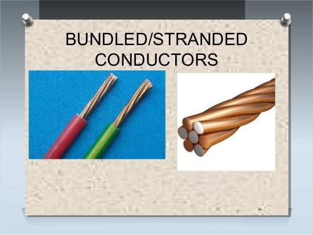
11.5 Bundled Conductors
be used in overhead transmission as well as distribution lines.
11.5 Bundled Conductors
Transmission at extra high voltages
(say above 220 kV) poses some problems such as significant corona loss and
excessive interference with nearby communication lines when only one conductor
per phase is used. This is because, at EHV level, the electric field gradient
at the surface of a single conductor is high enough to ionize the surrounding
air which causes corona loss and interference problems. The electric field
gradient can be reduced significantly by employing two or more conductors per
phase in close proximity. Two or more conductors per phase are connected at
intervals by spacers and are called as bundled conductors. The image at right
shows two conductors in bundled form per phase. Number of conductors in a
bundled conductor is greater for higher voltages.
12.Factors determining conductor sizes

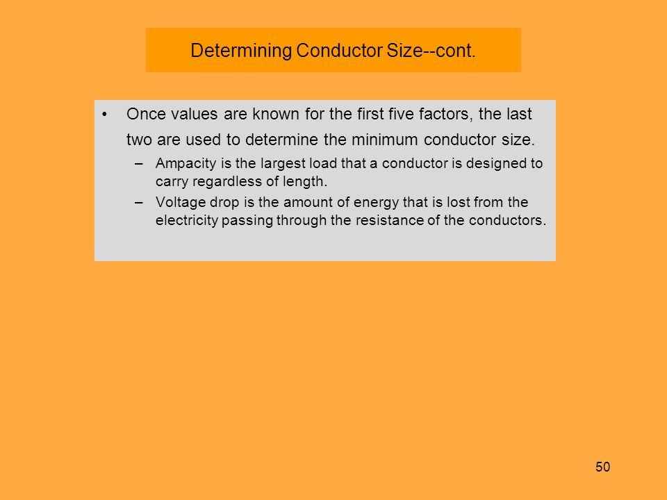
Voltage drop considerations:
The
conductor meets the minimum size requirement but transmits the power with an
acceptable loss. It is often expressed as a maximum voltage drop of 5%. The
total series impedance is equal to the maximum allowable voltage drop divided
by the maximum load current.
Thermal capacity:
The
conductor should be able to carry the maximum long term load current with out
over heating.The conductor is assumed to withstand a temperature of 75 c
without decrease in strength.Above this temperature, strength decreases.
Economic considerations:
The conductor is rarely seized to
meet the minimum requirements.The total cost per kilometer or mile must be
taken in to account as too the present worth of energy losses associated with
the conductor.There must also be some compensation for load growth.
13.POLES
The supporting structures for overhead
line conductors are various types of poles and towers called line supports.In
general, the line supports should have the following properties :
(i)
High mechanical strength to withstand the weight of conductors and wind loads
etc.
(ii) Light in weight without the loss of
mechanical strength.
(iii) Cheap in cost and economical to
maintain.
(iv) Longer life.
(v) Easy accessibility of conductors for
maintenance.
The line supports used for transmission and
distribution of electric power are of various types including wooden poles,
steel poles, R.C.C. poles and lattice steel towers.The choice of supporting
structure for a particular case depends upon the line span, X-sectional area,
line voltage, cost and local conditions.
Wooden poles : These are made of
seasoned wood (sal or chir) and are suitable for lines of moderate X-sectional
area and of relatively shorter spans, say upto 50 metres.Such supports are
cheap, easily available, provide insulating properties and, therefore, are
widely used for distribution purposes in rural areas as an economical
proposition.The wooden poles generally tend to rot below the ground level,
causing foundation failure.In order to prevent this, the portion of the pole
below the ground level is impregnated with preservative compounds like creosote
oil.Double pole structures of the ‘A’ or ‘H’ type are often used to obtain a
higher transverse strength than could be economically provided by means of
single poles.
The main objections to wooden supports are
:
(i) Tendency to rot below the ground level
(ii) Comparatively smaller life (20-25
years)
(iii) Cannot be used for voltages higher
than 20 kV
(iv) Less mechanical strength and require
periodical inspection.

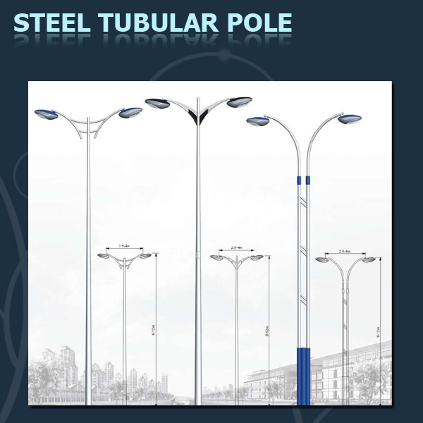
Steel poles :
The steel poles are often used as a substitute
for wooden poles.They possess greater mechanical strength, longer life and
permit longer spans to be used.Such poles are generally used for distribution
purposes in the cities.This type of supports need to be galvanised or painted
in order to prolong its life.The steel poles are of three types (i) rail poles
(ii) tubular poles and (iii) rolled steel joints.
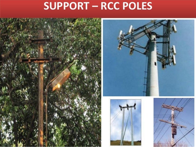
RCC poles :
The reinforced concrete poles have
become very popular as line supports in recent years.They have greater
mechanical strength, longer life and permit longer spans than steel
poles.Moreover, they give good outlook, require little maintenance and have
good insulating properties.Figure shows R.C.C. poles for single and double
circuit.The holes in the poles facilitate theclimbing of poles and at the same
time reduce the weight of line supports.The main difficulty with the use of
these poles is the high cost of transport owing to their heavy weight.Therefore,
such poles are often manufactured at the site in order to avoid heavy cost of
transportation.
14.TOWERS
A transmission tower or power tower
(electricity pylon in the United Kingdom and parts of Europe) is a tall
structure, usually a steel lattice tower, used to support an overhead power
line.
They are used in high-voltage AC and
DC systems, and come in a wide variety of shapes and sizes. Typical height
ranges from 15 to 55 m (49 to 180 ft), though the tallest are the 370 m (1,214
ft) towers of a 2,700 m (8,858 ft) span of Zhoushan Island Overhead Powerline
Tie. In addition to steel, other materials may be used, including concrete and
wood.
There are four major categories of
transmission towers: suspension, terminal, tension, and transposition. Some
transmission towers combine these basic functions. Transmission towers and
their overhead power lines are often considered to be a form of visual
pollution. Methods to reduce the visual effect include undergrounding.
TYPES OF TOWERS

Types of Transmission
Tower:
According
to different considerations, there are different types of transmission towers. The transmission line goes as per available
corridors. Due to unavailability of shortest distance straight corridor
transmission line has to deviate from its straight way when obstruction comes.
In total length of a long transmission line there may be several deviation
points.
According
to the angle of deviation there are four types of transmission tower-
A – type tower – angle of deviation 0 to 2deg.
B – type tower – angle of deviation 2 to 15deg.
C – type tower – angle of deviation 15 to 30deg.
D – type tower – angle of deviation 30 to 60deg.
As per the
force applied by the conductor on the cross arms, the transmission towers can
be categorized in another way-
Tangent
suspension tower and it is generally A - type tower.Angle tower or tension
tower or sometime it is called section tower. All B, C and D types of
transmission towers come under this category.
A part from the above customized type of tower, the
tower is designed to meet special usages listed below,
These are called special
type tower
River crossing tower
Railway/ Highway crossing tower
Transposition tower
Based on numbers of circuits carried by a
transmission tower, it can be classisfied as-
Single circuit tower
Double circuit tower
Multi circuit tower.
Transmission towers are used to
pass signal wires and electrical current from place to place. They are usually
made of steel and can run at times for long distances. Transmission towers are
most often used when there is a large amount of electrical current to be
distributed, usually between 115,000 and 765,000 volts. Several different
designs of transmission towers are in wide use in the world today.
Lattice steel towers
Lattice steel towers are made up of many
different steel structural components connected together with bolts or welded.
Many different types of lattice steel towers exist. These towers are also
called self-supporting transmission towers or free-standing towers, due to
their ability to support themselves. These towers are not always made of steel;
they can also be made of aluminum or galvanized steel.
.
.
Tubular steel poles
Tubular steel poles are
another of the major types of transmission towers. They are made up of hollow
steel poles. Tubular steel poles can be manufactured as one large piece, or as
several small pieces which fit together
.
.
Single and double circuit towers
Both tubular and lattice steel towers
can be designed so as to support either one or two circuits of electrical
current. Double-circuit towers hold the different conductors stacked atop one
another, while in single-circuit towers the conductors are lined up
horizontally.

GUYED TOWERS
Guyed towers take up a lot of space, and
are therefore only used in parts of the world where land use policy allows
them. They consist of two masts supported by four guys, or support cables.

Suspension straight
towers
Suspension
straight towers are a type of self-supporting tower that stands along straight
sections of a transmission route. These towers are also sometimes called
tangent towers. The only function of these types of towers is to suspend the
wires. They do not have to create or regulate tension in any way.

Suspension angle towers
Suspension angle towers are built when it is necessary for the route of
the electrical current to turn. These angle towers are usually designed so that
the axis of the cross-arm bisects the angle of the conductors. This is the most
efficient way to use the tower.

Anchor and angle tension towers
Anchor and angle tension towers are used to
sectionalize the routes. They terminate the conductors and they provide
containment of possible cascade failures.

15.TOWER ACCESSORIS

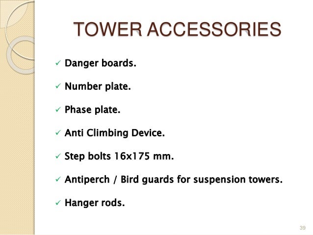
BIRD GUARDS
FONDATION BOLTS

EARTHING RODS

16.PROTECTION OF TOWER FOOTING
GENERAL:
Special measures for protection of
foundations shall be taken in respect of locations close to / in nallah, river
beds, etc. Protection of foundations is also to be provided in the case of
foundations located on the sloping ground of sand dunes or hills.
The above is to be done, based on site
conditions, by employing any or a combination of the following three methods
which are best suited for the site conditions.
a) Benching.
b) Protection against cutting of soil by flow
of water.
c) Rivetment.
BENCHING:
This method is generally used if the
soil is gently sloping and there is no
significant difference in the levels of the soil around the foundation. The
soil at the higher level is cut and spread in the lower level so that the soil
near the foundation becomes level.
PROTECTION AGAINST CUTTING OF SOIL BY FLOW OF
WATER:
This method is generally used where the
tower foundation is located at a distance from the edge of river / nallah, etc.
The foundation is protected by providing suitable crate of galvanized wire
netting and meshing packed with boulders.
RIVETMENT:
This
method is generally used where the
ground surface is irregular or where there is significant difference in
the levels of soil around the tower foundation. The rivetment protection is
provided in the form of stone masonry walls around those sides of the
foundation where such protection is required.
Depending on
the site conditions, the following are to be decided:
a) The side or sides on which the rivetment is to be
provided.
b) Height of the masonry wall.
c) Length of the masonry wall.
17. EARTHING
To
connect the metallic (conductive) Parts of an Electric appliance or
installations to the earth (ground) is called Earthing or Grounding.
In other
words, to connect the metallic parts of electric machinery and devices to the
earth plate or earth electrode (which is buried in the moisture earth) through
a thick conductor wire (which has very low resistance) for safety purpose is known
as Earthing or grounding.
To earth
or earthing rather, means to connect the part of electrical apparatus such as
metallic covering of metals, earth terminal of socket cables, stay wires that
do not carry current to the earth. Earthing can be said as the connection of
the neutral point of a power supply system to the earth so as to avoid or
minimize danger during discharge of electrical energy.
Need of Earthing or Grounding:
The
primary purpose of earthing is to avoid or minimize the danger of electrocution,
fire due to earth leakage of current through undesired path and to ensure that
the potential of a current carrying conductor does not rise with respect to the
earth than its designed insulation.
When
the metallic part of electrical appliances (parts that can conduct or allow
passage of electric current) comes in contact with a live wire, maybe due to
failure of installations or failure in cable insulation, the metal become
charged and static charge accumulates on it. If a person touches such a charged
metal, the result is a severe shock.
To
avoid such instances, the power supply systems and parts of appliances have to
be earthed so as to transfer the charge directly to the earth.
Basic needs of Earthing:
To protect
human lives as well as provide safety to electrical devices and appliances from
leakage current.
·
To keep voltage as constant in the
healthy phase (If fault occurs on any one phase).
·
To Protect Electric system and buildings
form lighting.
·
To serve as a return conductor in
electric traction system and communication.
·
To avoid the risk of fire in electrical
installation systems.
Different Terms used in Electrical
Earthing
Earth: The proper connection between electrical
installation systems via conductor to the buried plate in the earth is known as
Earth.
Earthed:
When an electrical device, appliance or wiring system connected to the earth
through earth electrode, it is known as earthed device or simple “Earthed”.
Solidly
Earthed: When an electric device, appliance or electrical
installation is connected to the earth electrode without a fuse, circuit
breaker or resistance/Impedance, It is called “solidly earthed”.
Earth
Electrode: When
a conductor (or conductive plate) buried in the earth for electrical earthing
system. It is known to be Earth Electrode. Earth electrodes are in different
shapes like, conductive plate, conductive rod, metal water pipe or any other
conductor with low resistance.
Earthing Lead:
The conductor wire or conductive strip connected between Earth electrode and
Electrical installation system and devices in called Earthing lead.
Earth Continuity Conductor:
The conductor wire, which
is connected among different electrical devices and appliances like,
distribution board, different plugs and appliances etc. in other words, the
wire between earthing lead and electrical device or appliance is called earth
continuity conductor. It may be in the shape of metal pipe (fully or partial),
or cable metallic sheath or flexible wire.
Sub Main Earthing Conductor: A wire connected between switch
board and distribution board i.e. that conductor is related to sub main
circuits.
Earth Resistance:
This is the total resistance between earth electrode and earth in Ω (Ohms).
Earth resistance is the algebraic sum of the resistances of earth continuity
conductor, earthing lead, earth electrode and earth.
Components of Earthing
System
A complete electrical
earthing system consists on the following basic components.
·
1.Earth continuity Conductor
· 2.
Earthing Lead
·
3.Earth Electrode
Earth continuity or Earth wire
That part of the earthing system which
interconnects the overall metallic parts of electrical installation e.g.
conduit, ducts, boxes, metallic shells of the switches, distribution boards,Switches,
fuses, Regulating and controlling devices, metallic parts of electrical
machines such as, motors, generators, transformers and the metallic framework
where electrical devices and components are installed is known as earth wire or
earth continuity conductor as shown in the fig.
The resistance of the earth continuity
conductor is very low. According to IEEE rules, resistance between consumer
earth terminal and earth Continuity conductor (at the end) should not be
increased than 1Ω. In simple words, resistance of earth wire should be less
than 1Ω.

Earthing Lead or
Earthing Joint
The conductor wire connected between
earth continuity conductor and earth electrode or earth plate is called
earthing joint or “Earthing lead”. The point where earth continuity conductor
and earth electrode meet is known as “connecting point” as shown in the fig
Earthing lead is the final part of the
earthing system which is connected to the earth electrode (which is
underground) through earth connecting point.
There should be minimum joints in earthing
lead as well as lower in size and straight in the direction.
Generally, copper wire
can be used as earthing lead but, copper strip is also used for high
installation and it can handle the high fault current because of wider area
than the copper wire.
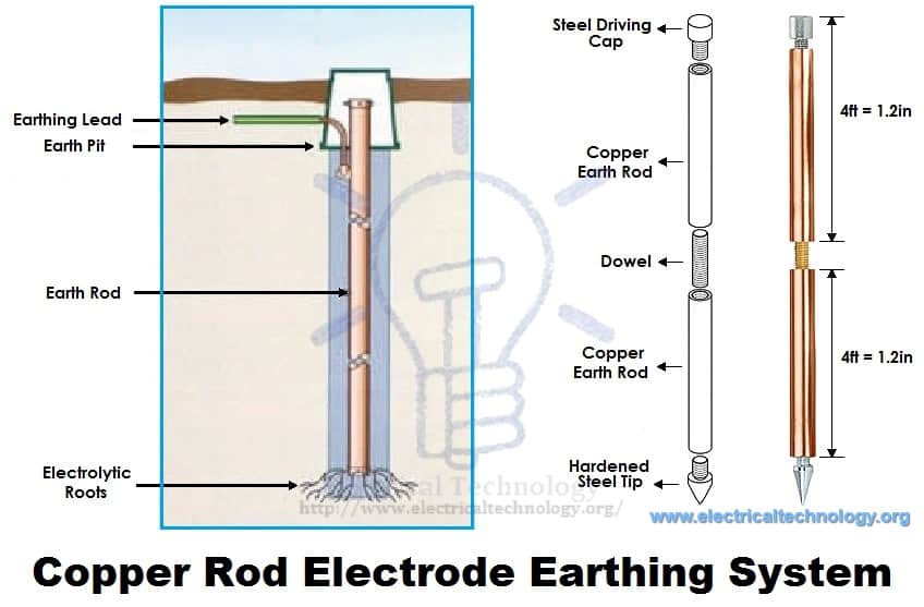
Earthing Electrode or Earth Plate
A metallic electrode or plate which is
buried in the earth (underground) and it is the last part of the electrical
earthing system. In simple words, the final underground metallic (plate) part
of the earthing system which is connected with earthing lead is called earth
plate or earth electrode.
A metallic plate, pipe or rode can be used
as an earth electrode which has very low resistance and carry the fault current
safely towards ground (earth).
A hard drawn bare
copper wire is also used as an earthing lead. In this method, all earth
conductors connected to a common (one or more) connecting points and then,
earthing lead is used to connect earth electrode (earth plat) to the connecting
point.
To increase the safety
factor of installation, two copper wires are used as earthing lead to connect
the device metallic body to the earth electrode or earth plate. I.e. if we use
two earth electrodes or earth plats, there would be four earthing leads. It
should not be considered that the two earth leads are used as parallel paths to
flow the fault currents but both paths should work properly to carry the fault
current because it is important for better safety.

18.
TYPES OF INSULATORS
There are several types of insulators but the most
commonly used are pin type, suspension type, strain insulator and shackle
insulator.
18.1 Pin type insulators :
The
part section of a pin type insulator is shown in Figure below.As the name
suggests, the pin type insulator is secured to the cross-arm on the pole.There
is a groove on the upper end of the insulator for housing the conductor.The
conductor passes through this groove and is bound by the annealed wire of the
same material as the conductor.
Pin type insulators are used for transmission and distribution of
electric power at voltages up to 33 kV.
Beyond operating voltage of 33 kV, thepin type insulators become too
bulky and hence uneconomical.

Causes of insulator failure :
Insulators are required to withstand both
mechanical and electrical stresses.The latter type is primarily due to line
voltage and may cause the breakdown of the insulator.The electrical breakdown
of the insulator can occur either by flash-over or puncture.In flash over, an
arc occurs between the line conductor and insulator pin (i.e., earth) and the
discharge jumps across the air gaps, following shortest distance.Figure below
shows the arcing distance (i.e. a + b + c) for the insulator.In case of
flash-over, the insulator will continue to act in its proper capacity unless
extreme heat produced by the arc destroys the insulator.
In case of puncture, the discharge occurs
from conductor to pin through the body of the insulator.When such breakdown is
involved, the insulator is permanently destroyed due to excessive heat.In
practice, sufficient thickness of porcelain is provided in the insulator to
avoid puncture by the line voltage. The ratio of puncture strength to flash
over voltage is known as safety factor i.e
Advantages of pin-type insulators:
1.Widely used on high voltage distribution lines
2.Having a better anti-fog performance
3.Easily handle and manufacture
4.Can be mounted as necessary, vertically or
horizontally.
18.2 Suspension type insulators :
The cost of pin type insulator increases
rapidly as the working voltage is increased. Therefore, this type of insulator
is not economical beyond 33 KV. For high
voltages (>33 KV), it is a usual practice to use suspension type
insulators shown in Figure below. They consist of a number of porcelain discs
connected in series by metal links in the form of a string. The conductor is
suspended at the bottom end of this string while the other end of the string is
secured to the cross-arm of the tower. Each unit or disc is designed for low
voltage, say 11 kV. The number of discs in series would obviously depend upon
the working voltage. For instance, if the working voltage is 66 kV, then six
discs in series will be provided on the string.

Advantages Of suspension type insulators:
(i) Suspension type
insulators are cheaper than pin type insulators for voltages beyond 33 kV.
(ii) Each unit or disc
of suspension type insulator is designed for low voltage, usually 11 kV.
Depending upon the
working voltage, the desired number of discs can be connected in series.
(iii) If any one disc
is damaged, the whole string does not become useless because the damaged disc
can be replaced by the sound one.
(iv) The suspension
arrangement provides greater flexibility to the line. The connection at the cross arm is such that
insulator string is free to swing in any direction and can take up the position
where mechanical stresses are minimum.
(v) In case of
increased demand on the transmission line, it is found more satisfactory to
supply the greater demand by raising the line voltage than to provide another
set of conductors. The additional insulation required for the raised voltage
can be easily obtained in the suspension arrangement by adding the desired
number of discs.
(vi) The suspension
type insulators are generally used with steel towers. As the conductors run below the earthed
cross-arm of the tower, therefore, this arrangement provides partial protection
from lightning.
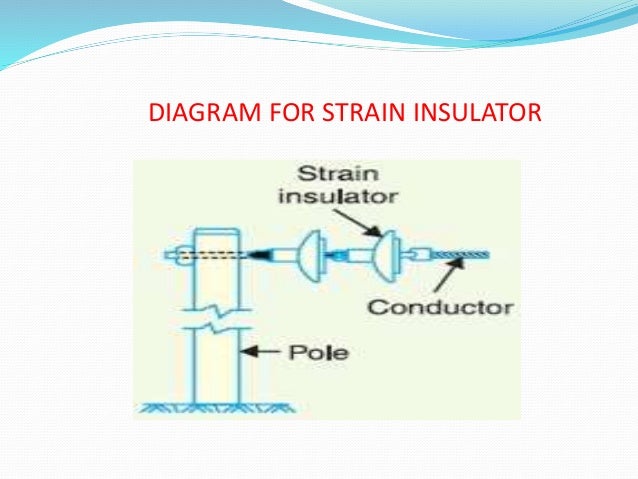
18.3 Strain insulators :
When there is a dead end of the line or
there is corner or sharp curve, the line is subjected to greater tension.In
order to relieve the line of excessive tension, strain insulators are used.For
low voltage lines (< 11 kV), shackle insulators are used as strain
insulators.However, for high voltage transmission lines, strain insulator
consists of an assembly of suspension insulators as shown in Figure. The discs
of strain insulators are used in the vertical plane. When the tension in lines
is exceedingly high, as at long river spans, two or more strings are used in
parallel.
18.4 Shackle insulators :
In early days, the shackle insulators were
used as strain insulators. But now a days they are frequently used for low
voltage distribution lines. Such insulators can be used either in a horizontal
position or in a vertical position. They can be directly fixed to the pole with
a bolt or to the cross arm. Figure below shows a shackle insulator fixed to the
pole. The conductor in the groove is fixed with a
soft binding wire.


20.BOQ OF 33 KV TRANSMISSION LINE
Discription of work


5. Supply of 33KV 100x50mm Channel cross arms with back clamp


soft binding wire.
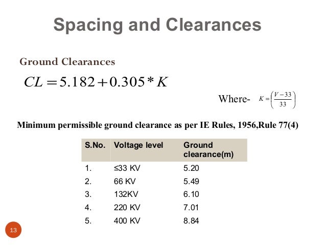
Ground
Clearance:
Ground clearence means the height of middle of
line between two towers from ground... it is so designed as the sag is minimum
and stress on transmission line is also minimum.
Clearance above ground of the lowest conductor
(including guard – wires) is to meet the following conditions:
1. No conductor of an overhead line including
service lines erected across a street shall be at any part there of be at a
height less than:
a) For low & medium voltage line (i.e. up
to 650 volts) – 5.791 mts
b) For high voltage lines (up to 33 KV) –
6.096 mts
2. Along a street: a) For low& medium
voltage lines _5.486 mts
b) For high voltage lines(up to 33 KV) _ 5.794
mts
3. Elsewhere other than
1,2 above
a) For high voltage up to 11KV - 4.572 mts
Clearance from Building, Structure etc a. The
vertical clearance above building (from the highest point) on the basis of
maximum sag shall not be less than (2.439 m) 8 ft for low and medium voltage
line (up to 650 volts) and (3.64 m) 12 ft for 11 and 33 KV line. b. The
horizontal clearance is to be 4 ft (1.219 m) upto 11 KV line and 6 ft (1.820 m)
for 33 KV line.
i)
It may be
mentioned that for Railway crossing, rules as prescribed by Railways are to be
followed
ii)
ii) Similarly the lines crossing or in proximity
to the telecommunication lines, the overhead line is to be protected as per
code of practice laid down by PTCC coordination committee.
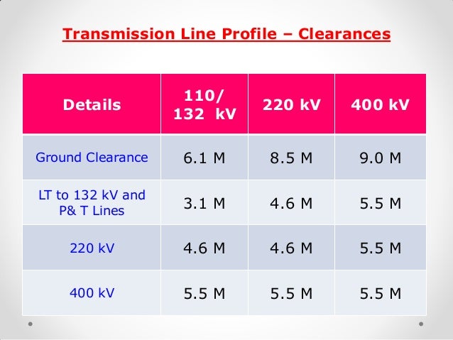
CLEARANCE ABOVE GROUNDS
(Clause 77 of Indian
Electricity Rules)
m. m.
|
|
33 KV
|
5100
|
66 KV
|
5490
|
132 KV
|
6100
|
220 KV
|
7015
|
400 KV
|
8840
|
The minimum clearances
of conductor over rivers, which are not navigable, shall be kept 3.05 m over
maximum flood level.
The minimum clearances
between the conductors of a power line and telecommunication cable shall be:
132 kV
|
2.44 m
|
220 kV
|
2.74 m
|
400 kV
|
4.88 m
|
The minimum spacing
between power lines shall be:
132 kV
|
2.75 m
|
220 kV
|
4.55 m
|
400 kV
|
6.00m
|
The spacing of
conductors is determined by considerations, which are partly electrical and
partly mechanical. Usually conductors will swing synchronously (in phase) with
the wind, but with long spans and small size of conductors, there is always
possibility of the conductors swinging non- synchronously, and the size of the
conductor and the maximum sag at the centre of the span are factors, which
should be taken into account in determining the phase distance apart at which
they should strung. As a rule of thumb, minimum horizontal spacing between
conductors should not be less than 1% of the span length in order to minimize
the risk of phases coming into contact with each other during swing.
There are number of
empirical formula in use, deduced from spacing, which have successfully
operated in practice:
NESC, USA formula
Horizontal spacing in
cm,
Where A = 0.762 cm per
kV line voltage
S = Sag in cm, and
L = Length of insulator
string in cm
Swedish formula
Horizontal spacing in
cm,
Where S = Sag in cm and
E = Line voltage in kV
French formula
Horizontal spacing in
cm,
Where S = Sag in cm
L = Length of insulator
string in cm
E = Line voltage in kV
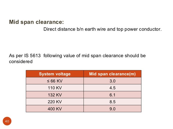
Tower top clearance
Tower top clearance is
the vertical clearance between earthwire and top conductor, which is governed
by the angle of shielding. The shield angle varies from about 250 to
300,depending on the configuration of conductors. Tower top clearance shall be
taken 1.5 and 2.25 m for 132 kV and 220 kV respectively for 00 swing.
Clearances from building:
(a) Where a high or
extra high voltage over head line passes above or adjacent to any
building or part of a
building, it shall have on the basis of maximum sag, a vertical
clearance above the
highest part of the building immediately under such line, of not
less than :
1
|
for high
voltage line upto and including.
33
KV
|
3.658 mtrs. (12 ft.)
|
2
|
for extra high voltage lines
|
3.685 mtrs. (12 ft.)
plus 0.305 mtrs. (1
ft.) for every additional 33 KV or part thereof.
|
(
(b) The horizontal clearance
between the nearest conductor and any part of such
building shall on the
basis of maximum deflection due to wind pressure, be not less
than :
1
|
for
high voltage line up to andincluding11KV
|
1.219 mtrs. (4ft.)
|
2
|
for
high voltage line above 11 KV and up to and including 33 KV
|
1.829
mtrs. (6ft.)
|
3
|
for
extra high voltage line
|
1.829mtrs.(6ft)plus 0:305 mtrs, (1 ft.)for
every additional 33 KV or part thereof.
|
FOREST CLEARANCE WHERE NO TREES ARE REQUIRED TO BE
FELLED
Only
following information shall be required to be submitted in the prescribed
format for obtaining forest clearance in case of those transmission lines,
which do not involve felling of trees :—
i) Geographical location of transmission in
along with Index map.
ii) Purpose for which forest land is required to
be used.
iii) Area of forest
land to be used.
iv) Legal status of the forest land.
v) Whether forest land is Ear-marked for any
National Garden/Park wild life, part
reserved wild life, vegetation or rehabilitation which
are in danger of extinction.
vi) Whether there is any other alternative route
to save forest area, and whether the forest area being used, is minimum
required for the purpose. In this regard a certificate of the Regional Forest
Officer shall have to be submitted along with the proposal.
vii) Compensatory A
forestation Schemes.
viii) A certificate
clearly stating that no felling of tree is required in the proposal.
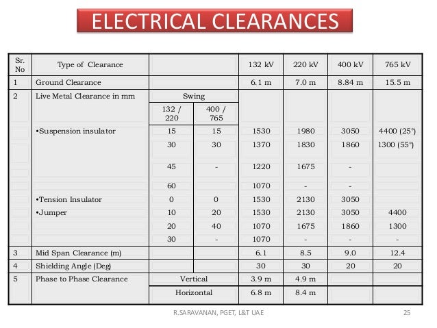
ELECTRICAL CLEARANCE:
The
minimum distance permitted between fixed structures and parts energized at
contact line voltage is said to be a electrical clearance.
As per 1SS 162—1961 minimum electrical
clearance from live part to earth and safety clearance in case of different
voltage must be kept as follows :
VOLTAGE
|
ELECTRICALCLEARANCE(mm) PhaseEarth/ PhasePhase
|
SAFETY CLEARANCE IN
SIS (mm)
|
KV
|
||
33
|
381 432
|
2740
|
66
|
658 786
|
3050
|
132
|
1127 1473
|
3810
|
220
|
2082 2388
|
4570
|
4000
|
350 4000
|
6100
|
MINIMUM CLEARANCE BETWEEN POWER LINES:
"Power line
crossing" means an electrical overhead line or under-ground cable placed
across railway track(s) for the transmission and/or distribution of electrical
energy. It may also be referred to as a "Crossing" in these
Regulations.
Nominal System Voltage
of line to be crossed:
KV
11 33 66 132 220 400
11 2.44 2.44 2.44 3.05 4.58 6.10
33 2.44 2.44 3.05 4.58 6.10
66 2.44 3.05 4.58 6.10
132 3.05 4.58 6.10
220 4.58 6.10
400 6.10
400 6.10
CLEARANCE FROM RAILWAY TRACKS:
(As per Regulation for
Electrical Crossing of Railway Tracks 1963)
The relevant provisions for the crossings of
Railway Tracks by the power lines are as under: The minimum height above rail
level of the lowest portion of any conductor under conditions of maximum sag
are as follows in accordance with the Regulations for Electrical Crossings of
Railway Tracks, 1963:
(i) FOR UNELECTRIFIED TRACKS OR TRACKS
ELECTRIFIED ON 1500 VOLTS D.C.
Broad
Gauge Meter and Narrow Gauge
Inside Outside Inside Outside
station station station station
limits limits limits limits
(mm) (mm) (mm) (mm)
66 KV
10,300 7,900 9,100 6,700
132 KV 10,900 8,500 9,800 7,300
220 KV 11,200 8,800 10,000 7,600
220 KV 11,200 8,800 10,000 7,600
440 KV* 13,600 11,200
12,400 10,000
(ii) TRACKS ELECTRIFIED
ON 25 KV A.C.
For Broad, Meter and Narrow
Gauges
Inside Outside
station station
limits limits
(mm) (mm)
66 KV 13,000 11,000
132 KV 14,000 12,000
220 KV 15,300 13,300
440 KV* 16,300 14,300
* Tentatively assumed.
No conductor of an
extra high voltage overhead line crossing a tramway or trolley bus using
trolley wires should have a clearance less than 3050 mm above the trolley line.
The provisions of the
above Regulations must be kept in mind while carrying out the patrolling of
Transmission lines. Any deviation noticed should be reported / attended on
top-priority
CLEARANCE OF RIGHT OF WAY:
An
electric transmission line right-of-way (ROW) is a strip of land used by Electrical
utilities to construct operate, maintain and repair the transmission line
facilities.
The
width of a right-of-way depends on the voltage of the line and the height of
the structures. The right-of-way generally must be clear of unauthorized
structures that could interfere with a power line.
The width of right of way for the various line
voltages is repeated below.
Line Voltage
|
Width of Right of Way
|
132 kV
|
27 metres
|
220 kV
|
35 metres
|
400 kV
|
52 metres
|
i)
A drawing
showing the requirements of line clearance within the right of way is given
atAppendix – A.
ii)
Cutting of
trees, shrubs, bushes, etc. in the right of way is to be got done as shown in
thedrawing above. All trees, shrubs, bushes, etc. which infringe on the
clearances are to becut.
iii)
Small bush
growth, shrubs and trees whose height is not expected to rise beyond 3 metersmay
be allowed to remain.
iv)
Grass growth on
the boundary walls (Dola) of agriculture fields which can grow to a heightsuch
as to infringe on the clearance are to be cut.
v)
Trees outside
right of way but of such height as may infringe on line clearance are to
betrimmed accordingly.
vi)
Trees or bushes
growing inside or very close to the legs of towers shall be cut / removed


20.BOQ OF 33 KV TRANSMISSION LINE
Discription of work
1.Supply and erection of M+6 Towers,
Excavation of pit and setting of stubsposition
duly filling it with CC mix ( 20mm HBG metal) and complete erection of M+6 Towers
Qty
|
Unit
|
|
Material
|
3
|
EA
|
Labour
|
3
|
2 Supply of 7/4 RS
Joist 12Mtr Box poles, Excavation of pit and erection of pole into position by
mass concreteing below the ground level and coping of the pole above the ground level Qty
Unit
Material 17 EA
Labour
17 EA
3.
Supply of 100Sqmm AAA Doc Conductor and stringing 100Sqmm AAA conductor.
Qty Unit
Qty Unit
Material 6.25 KM
Labour 6.25 KM
4
Supply of 33KV 100x50mm V Cross arms with back clamps, top fitting completed
nuts & bolts
Qty Unit
Material 55 No
Labour 55 No
Labour 55 No
5. Supply of 33KV 100x50mm Channel cross arms with back clamp
Qty
Unit
Material 5 No
Labour
5 No
6.
Supply and erection of 33KV Pin Insulators with pins
Qty Unit
Material 125 No
Labour 125 No
7.
Supply and erection 33KV Polymer Disc Insulators with metal parts Qty Unit
Material 50
No
Labour 50 No

8.
Supply and Erection of 40 mm GI Earth flat
Qty Unit
Material 7 No
Labour 7 No

9.
Supply & Painting two coat red oxide and two coat Aluminium Painting towers
and RS Joist Pols, V X Arms, Channels, Back Clamps, top clamps
Qty Unit
Material LS
Labour
LS
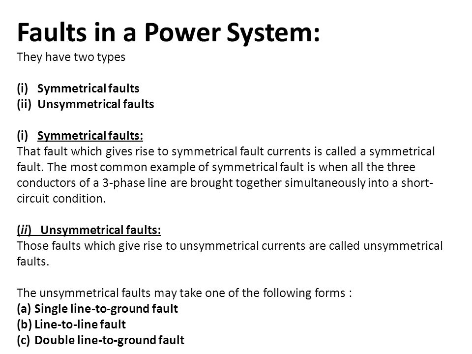
21.Types of Faults in Electrical Power Systems
Types of Faults
Electrical
faults in three-phase power system mainly classified into two types, namely
open and short circuit faults. Further, these faults can be symmetrical or
unsymmetrical faults. Let us discuss these faults in detail.
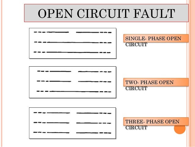
Open Circuit Faults
These
faults occur due to the failure of one or more conductors. The figure below
illustrates the open circuit faults for single, two and three phases (or
conductors) open condition.
The
most common causes of these faults include joint failures of cables and
overhead lines, and failure of one or more phase of circuit breaker and also
due to melting of a fuse or conductor in one or more phases.
Open
circuit faults are also called as series faults. These are unsymmetrical or
unbalanced type of faults except three phase open fault.
Consider
that a transmission line is working with a balanced load before the occurrence
of open circuit fault. If one of the phase gets melted, the actual loading of
the alternator is reduced and this cause to raise the acceleration of the
alternator, thereby it runs at a speed slightly greater than synchronous speed.
This over speed causes over voltages in other transmission lines.
Thus,
single and two phase open conditions can produce the unbalance of the power
system voltages and currents that causes great damage to the equipments.
Causes
Broken
conductor and malfunctioning of circuit breaker in one or more phases.
Effects
1. Abnormal operation of the system
2. Danger to the personnel as well as animals
3. Exceeding the voltages beyond normal values in
certain parts of the network, which further leads to insulation failures and
developing of short circuit faults.
Although
open circuit faults can be tolerated for longer periods than short circuit
faults, these must be removed as early as possible to reduce the greater
damage.
Short Circuit Faults
A
short circuit can be defined as an abnormal connection of very low impedance
between two points of different potential, whether made intentionally or
accidentally.
These
are the most common and severe kind of faults, resulting in the flow of
abnormal high currents through the equipment or transmission lines. If these
faults are allowed to persist even for a short period, it leads to the
extensive damage to the equipment.
Short
circuit faults are also called as shunt faults. These faults are caused due to
the insulation failure between phase conductors or between earth and phase
conductors or both.
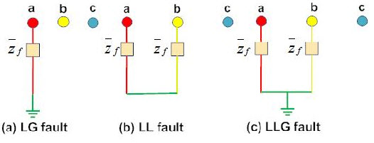
The
various possible short circuit fault conditions include three phase to earth,
three phase clear of earth, phase to phase, single phase to earth, two phase to
earth and phase to phase plus single phase to earth as shown in figure.
The
three phase fault clear of earth and three phase fault to earth are balanced or
symmetrical short circuit faults while other remaining faults are unsymmetrical
faults.
Causes
These
may be due to internal or external effects.
Internal effects include breakdown of transmission
lines or equipment, aging of insulation, deterioration of insulation in
generator, transformer and other electrical equipments, improper installations
and inadequate design.
2. External effects include overloading of equipments,
insulation failure due to lighting surges and mechanical damage by public.
Effects
1. Arcing faults can lead to fire and explosion in
equipments such as transformers and circuit breakers.
2. Abnormal currents cause the equipments to get overheated,
which further leads to reduction of life span of their insulation.
3. The operating voltages of the system can go below or
above their acceptance values that creates harmful effect to the service
rendered by the power system.
4. The power flow is severely restricted or even
completely blocked as long as the short circuit fault persists.
Symmetrical and Unsymmetrical
Faults
As
discussed above that faults are mainly classified into open and short circuit
faults and again these can be symmetrical or unsymmetrical faults.
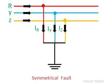
Symmetrical Faults
A symmetrical fault gives rise to
symmetrical fault currents that are displaced with 1200 each other. Symmetrical
fault is also called as balanced fault. This fault occurs when all the three
phases are simultaneously short circuited.
These faults rarely occur in practice as
compared with unsymmetrical faults. Two kinds of symmetrical faults include
line to line to line (L-L-L) and line to line to line to ground (L-L-L-G) as
shown in figure below.
A rough occurrence of symmetrical faults is
in the range of 2 to 5% of the total system faults. However, if these faults
occur, they cause a very severe damage to the equipments even though the system
remains in balanced condition.
The analysis of these faults is required for
selecting the rupturing capacity of the circuit breakers, choosing set-phase
relays and other protective switchgear. These faults are analyzed on per phase
basis using bus impedance matrix or Thevenins’s theorem.
Unsymmetrical Faults
The
most common faults that occur in the power system network are unsymmetrical
faults. This kind of fault gives rise to unsymmetrical fault currents (having
different magnitudes with unequal phase displacement). These faults are also
called as unbalanced faults as it causes unbalanced currents in the system.
Up
to the above discussion, unsymmetrical faults include both open circuit faults
(single and two phase open condition) and short circuit faults (excluding
L-L-L-G and L-L-L).
The
figure below shows the three types of symmetrical faults occurred due to the
short circuit conditions, namely phase or line to ground (L-G) fault, phase to
phase (L-L) fault and double line to ground (L-L-G) fault.
A single
line-to-ground (LG) fault is one of the most common faults and experiences show
that 70-80 percent of the faults that occur in power system are of this type.
This forms a short circuit path between the line and ground. These are very
less severe faults compared to other faults.
A
line to line fault occur when a live conductor get in contact with other live
conductor. Heavy winds are the major cause for this fault during which swinging
of overhead conductors may touch together. These are less severe faults and its
occurrence range may be between 15-20%.
In
double line to ground faults, two lines come into the contact with each other
as well as with ground. These are severe faults and the occurrence these faults
is about 10% when compared with total system faults.
Unsymmetrical
faults are analyzed using methods of unsymmetrical components in order to
determine the voltage and currents in all parts of the system. The analysis of
these faults is more difficult compared to symmetrical faults.
This
analysis is necessary for determining the size of a circuit breaker for largest
short circuit current. The greater current usually occurs for either L-G or L-L
fault.
Protection Devices
against Faults
When
the fault occurs in any part of the system, it must be cleared in a very short
period in order to avoid greater damage to equipments and personnel and also to
avoid interruption of power to the customers.
The
fault clearing system uses various protection devices such as relays and
circuit breakers to detect and clear the fault.
Some
of these fault clearing or faults limiting devices are given below.
Fuse
It
opens the circuit whenever a fault exists in the system. It consists of a thin
copper wire enclosed in a glass or a casing with two metallic contacts. The
high fault current rises the temperature of the wire and hence it melts. A fuse
necessitates the manual replacement of wire each time when it blows.
Circuit Breaker
It
is the most common protection device that can make or break the circuit either
manually or through remote control under normal operating conditions.
There
are several types of circuit breakers available depending on the operating
voltage, including air brake, oil, vacuum and SF6 circuit breakers. For more
information on circuit breakers, follow the link attached.
Protective Relays
These
are the fault detecting devices. These devices detect the fault and initiate
the operation of the circuit breaker so as to isolate the faulty circuit. A
relay consists of a magnetic coil and contacts (NC and NO). The fault current
energizes the coil and this causes to produce the field, thereby the contacts
get operated.
Some
of the types of protective relays include
1. Magnitude relays
2. Impedance relays
3. Directional relays
4. Pilot relays
5. Differential relays

Lighting Arrestor
Surges
in the power system network caused when lightning strikes on transmission lines
and equipments. This causes high voltage and currents in the system. These
lighting faults are reduced by placing lighting arrestors at transmission
equipments.
22.TESTING AND COMMISSIONING
TESTING:
After final checking is carried out and there
are no defects / shortcomings in the work of the transmission line, the line is
considered as having been completed and clear forenergizing.
Pamphlets bearing the warning notice as shown
in Appendix – A are got circulated in thearea through which the transmission
line is passing.
The
concerning Executive Engineer shall be present at the time of charging the
transmissionline who shall ensure that all testing and checking has been done
and approval of therelevant authorities has been obtained.
Before commissioning the line, the tests
given below are to be carried out.
INSULATION RESISTANCE TEST:
This test is carried with a motor driven
megger / insulation tester of at least 5 kV rating.This test is carried out to
ascertain the insulation condition of the line.
Measures for ensuring safety from induced high
voltages in the lines should be taken before carrying out this test.
The line is kept open at the other end. The
insulation resistance is measured between each phase and ground, and between
the phases. The ambient temperature and weather conditions are noted for future
reference.
The insulation resistance values are dependent
on the ambient temperature and weather conditions prevailing at the time when
these are measured. Therefore no comparable values are prescribed. However, the
values should not be ZERO. The observed values are recorded.
Conductor Continuity Test:
The electrical resistance of the
conductors is to be measured with a Wheatstone Bridge or other suitable
instrument. This test is carried out to verify that each conductor of the transmission
line is properly connected electrically. This is verified by comparing with the
electrical resistance of a continuous conductor of the same size and length
after correcting it to the temperature at which measurement has been made.
Measures for ensuring safety from
induced high voltages in the lines should be taken before carrying out this
test.
For measurement of the resistance, the line is
got earthed at the other end. The resistance of each phase to ground is
measured. The ambient temperature is noted for reference. The observed values
are recorded and compared as given at para below.
The maximum values of electrical resistance at
20°C of the conductors used in the transmission lines are given below as per IS
398 (Part 2) – 1996 / IS 398 (Part 5) – 1992
No
|
Transmission line voltage
|
Code name of conductor
|
Resistance
ohms per km
|
Resistance
ohms per km per phase
|
1
|
400 KV
|
ACSR Moos
|
0.05552
|
0.02776
|
2
|
220 kV
|
ACSR Zebra
|
0.06868
|
0.06868
|
3
|
132 kV
|
ACSR Panther
|
0.13900
|
0.13900
|
23. General applications of transmission
lines
Transferring signals from one point to another
Electrical transmission lines are very widely used to transmit high frequency
signals over long or short distances with minimum power loss. One familiar
example is the down lead from a TV or radio aerial to the receiver.
Signal transfer
Electrical transmission lines are very widely
used to transmit high frequency signals over long or short distances with
minimum power loss. One familiar example is the down lead from a TV or radio
aerial to the receiver.
Pulse generation
Transmission lines are also used as pulse
generators. By charging the transmission line and then discharging it into a
resistive load, a rectangular pulse equal in length to twice the electrical
length of the line can be obtained, although with half the voltage. A Blumlein
transmission line is a related pulse forming device that overcomes this
limitation. These are sometimes used as the pulsed energy sources for radar
transmitters and other devices.
Stub filters
If a short-circuited or open-circuited
transmission line is wired in parallel with a line used to transfer signals
from point A to point B, then it will function as a filter. The method for
making stubs is similar to the method for using Lecher lines for crude
frequency measurement, but it is 'working backwards'. One method recommended in
the RSGB's radio communication handbook is to take an open-circuited length of
transmission line wired in parallel with the feeder delivering signals from an
aerial. By cutting the free end of the transmission line, a minimum in the
strength of the signal observed at a receiver can be found. At this stage the
stub filter will reject this frequency and the odd harmonics, but if the free end
of the stub is shorted then the stub will become a filter rejecting the even
harmonics.
24.General considerations
Design
should satisfy
1. All the electrical and
mechanical considerations
2. Current carrying
capacity(required power transfer can take pace with out
excessive
voltage drop)
3. Line losses should be slow and
line should cope to system voltage.
4. Line conductors, supports cross
arm should cope with worst weather conditions
and give satisfactory service with
out much maintenance.
5 .Tension
in the conductor should be below breaking load(SAG)and reasonable FOS
should be used.
mounika
mounika
Testing:.........
A line support should have high mechanical strength to bear the conductor weight,wind load etc and the maintenance should be easy and cost should be very low.
ReplyDeleteTransformer Manufacturer in India | Wire harness manufacturer in India
I would highly recommend Le_ meridian funding services to any person in need financial help and they will keep you on top of high directories for any further needs. Once again I commend yourself and your staff for extraordinary service and customer service, as this is a great asset to your company and a pleasant experience to customers such as myself. Wishing you all the best for the future.Le meridian funding service is best way to get an easy loan,here is there email..lfdsloans@lemeridianfds.com Or talk to Mr Benjamin On WhatsApp Via_+1-989-394-3740 Thank You for helping me with loan once again in my sincerely heart I'm forever grateful.
ReplyDeleteWow, I came to learn about machines, and your information is absolutely amazing! For more insights and if your are looking for the Tubular poles
ReplyDelete! We provide the best quality poles in India renowned and manufacturers !